| CONTROLLERS
|
| TOUR
|
| TMA 4882-27 OVERVIEW |
| TMA VXI-27 OVERVIEW |
| TMA VXI-27 COMMUNICATION |
| TMA VXI-27 SOFT PANEL DOWNLOAD |
| TMA VXI-27 SOFT PANEL INSTRUCTIONS |
| MST 488-27 OVERVIEW |
| MANUALS |
TO START THE PROGRAM.
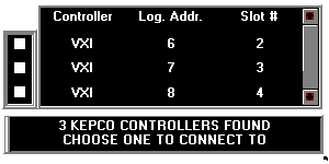
From FILE MANAGER, double-click on the file kpvxdemo.exe . The first screen (shown below) gives you a choice of three slots (2, 3, 4). These correspond to logical address 6, 7, and 8, respectively.

NOTE: The panel images shown here are illustrations ONLY! To see the working panels, start the program as described above.
Select a logical address/slot by clicking on one of the boxes at the left. This corresponds to the slot in the VXI mainframe holding the TMA VXI-27 Controller.
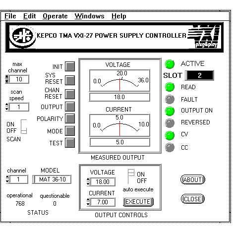
Once the slot has been selected, you will see the "virtual" panel of the Kepco power supply.

The virtual panel is completely operational, representing a system of five Kepco power supplies connected to the TMA VXI-27 plug&play controller. (The illustration above is not operational; start the program as described above to see the operating virtual panel.)
The following exercise illustrates the system's capabilities, however you are encouraged to explore the features on your own, choosing any of the Kepco power supplies connected to the system.
TO EXIT THE PROGRAM.
To exit the program, click on FILE and CLOSE at the top of the panel.To stop the program and restart, click on the CLOSE button at the lower right of the panel. Then click on OPERATE and RUN at the top off the panel to reinitialize.
UNDERSTANDING THE CONTROLS.
When you first run the demonstration program, click on HELP and SHOW HELP. Then move the cursor over each control and indicator on the panel. Help text will appear and explain the function of each.
SELECT THE CHANNEL.
Click on the arrows on the CHANNEL box at the lower left. You will see the five simulated Kepco power supply Models connected to the system.
SET THE VOLTAGE/CURRENT.
Channel 1 is connected to a simulated MAT 36-10 power supply (Maximum voltage, EMAX = 36V, Maximum current, IMAX = 10A). For demonstration purposes a simulated load equal to EMAX/IMAX is connected to each simulated power supply. In the case of the MAT 36-10, the load is 3.6 ohms.When the system is first initialized, the MAT 36-10 on channel 1 is in Constant Voltage (CV) mode with the output off. In the OUTPUT CONTROLS box at the lower center, if you click on the arrows you can increase or decrease the voltage and current.
As an exercise, set the voltage to 18 and current to 7. Since the power supply is in Constant Voltage mode, this means the current limit is 7 amperes. The output is off and EXECUTE has not been clicked, so the meters will indicate zero for voltage and current.
APPLY PROGRAMMED SETTINGS TO THE LOAD.
Click on the OUTPUT button to the left of the meters to turn on the output (connect the load). The OUTPUT ON indicator turns green but the output voltage and current still read zero.Click on EXECUTE. The programmed values for voltage and current limit are now applied to the load and the VOLTAGE and CURRENT meters represent the measured voltage and current. Note that the meters give both a digital and analog representation of voltage and current. If you click the ON/OFF switch above the EXECUTE button to ON, the autoexecute function is enabled, so that programmed changes in voltage or current are immediately applied to the load without clicking on EXECUTE each time.
IF YOU EXCEED THE CURRENT/VOLTAGE LIMIT.
As an exercise, increase the voltage to 26. You will notice the FAULT indicator goes on, since 26 volts applied to a 3.6-ohm load will produce a current that exceeds the 7 Ampere limit. You will notice that the STATUS - OPERATIONAL and QUESTIONABLE registers have values of 768 (voltage mode and relay closed) and 1024 (overload), respectively. Since the power supply has been limited to 7 Amps, it automatically switches to Constant Current mode (CC on, CV off).If you increase the current limit to 8, the FAULT indicator goes off and the mode switches back to CV. If you leave the current limit at 7 and click on the MODE button, the power supply will be programmed to CC mode, and the FAULT indicator will go off since the voltage (25.2V) does not exceed the programmed voltage limit (26V).