Approaches to Implementing Fault Tolerant Power Systems
By Mark Kupferberg,
Vice-president,
Manufacturing & Engineering,
Kepco, Inc., Flushing, NY

How do fault tolerant power systems end up in modern electronic systems?
Often it goes likes this:
Salesman: I can get an order for a hundred systems, but our competition
is offering a redundant power system. What can you do?
Engineer: Why would anyone need redundant power supplies? Our system
will be replaced by the next generation product long before the power supply
fails. Does the customer need 24 hours a day, and 7 day a week availability?
Salesman: No, but the customer thinks redundancy is better and our
competition has it. Can't you just add another power supply and an isolation
diode?
The typical Engineering response to this type of market driven requirement is
to do just as Sales suggests and create redundancy by basically duplicating the
original power system. Even in applications where fault tolerance is a
necessity, nuclear power generation or air traffic control, and where redundant
power is required as part of the original design, often the same basic approach
of doubling the number of power modules is used. This approach comes from using
the N+X formula to derive the number of devices needed. N represents the
number of power modules required to support the load's total power
requirements. X represents the number of power modules that can fail without
interrupting operations of the load. Since X is often equal to 1, the
redundancy formula, N+X , is known as N+1.
A common approach in applying this formula is to develop a power budget
for the load. An engineer then specifies a power supply system where a single
power module will provide the total load power requirement. Limited by space
and budget constraints and other application requirements, the depth of
redundancy may then be specified. (N+1 or N+2. . .) Often, just one additional
power module is specified to provide the redundancy. For example, if the load
has a 300 watt power requirement, the power system would consist of two 300
watt power modules. This configuration may be described as 1+1 using the N+X
formula.
A 1+1 redundant power system design yields a workable fault tolerant design,
but there are other approaches that designers may want to consider. A 1+1
design inherently requires that you buy twice as many watts as the system power
requirements. If the load's power budget changes, there is limited flexibility
(without redesigning the power system) to use modules at a different wattage
level. The ability to do field upgrades to a 1+1 redundancy power system may
also be limited by the need to change wiring and re-mount components. Also, a
1+1 formulation limits a given power system's use across different products
with different load power requirements.
An alternative approach is to apply the N+1 formula with an N greater than one.
This implies using multiple smaller power modules to configure the power
system. Tandem Computer (now a division of Compaq Computer) used this
approach years ago in designing and marketing fault tolerant computers. This
approach was a cornerstone of Tandem's phenomenal growth in the late 1970's and
1980's. Tandem realized that as the value of N went up, the cost of redundancy
went down as the percentage of capacity that needed to be duplicated dropped
from 100 percent to 10 percent or less. Tandem successfully showed its
customers that by using smaller Central Processing Units (CPUs) as building
blocks, it could provide fault tolerant systems for much less than its
competitors because it could use CPUs capable of fewer MIPS to achieve the
desired result. (MIPS are Millions of Instructions Per Second.)
The same logic applies to the configuration of fault tolerant power systems.
If, to achieve redundancy you double the power, you also double the cost of the
power. The bigger the size of the power module, the more pronounced this
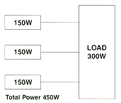
effect. Compare the N>1 approach for a power system supporting a 300 watt load
to the N=1 approach illustrated in table 1. Using the N=1 approach, the power
system would have two 300 watt power modules with total system power of 600
watts. With N=2, the system would have three 150 watt power modules with total
system power of 450 watts. Using Kepco's HSF line of hot swappable redundant
power modules as a basis for doing the cost comparison, the N=2 configuration
would cost about 14% less than the N=1 approach.
Table 1
| |
Value of N
|
N=1
 |
N=2
 > > |
| Load (Watts) |
300W
|
300W
|
| Size of individual modules |
300W
|
150W
|
| Number of power modules |
2
|
3
|
| Total system power |
600W
|
450W
|
While the direct cost savings associated with using the N=2 design are
significant, the other benefits associated with it may be even more important.
First, because of the modular character of the design and the relatively small
increment in the size of the power module, the same basic power system could be
used for both conventional and fault tolerant configurations. This allows the
system builder to have one basic design, supported by only one type of power
module. Having to buy, inventory and support only a single power module has
important overhead cost implications. The economies derived from buying a
single size module in higher volumes also tend to drive down acquisition costs.
Second, responsiveness to customer requirements is increased. Because the power
system can be configured to customer order from standard power modules, the
lead time associated with procuring the power system can be reduced or
eliminated. In this example, two power modules could be used for a
non-redundant configuration. Adding a third module would provide fault
tolerance. If the end customer wanted a greater depth of redundancy a fourth
module may be added.
Third is increased flexibility. In a world where customers increasingly want
products that are tailored to their requirements, the need to iterate
existing core designs significantly affects the marketability of a company's
products. Using larger numbers of smaller power modules to create
tailored systems makes this practical. In the above example, if the load
requirements grow 50% to 450 watts, all that is required is to slide in an
additional 150 watt module.
Fourth is the ability to generate additional revenue through field upgrade of
products. The addition of power modules provides increased systems power to
support the field add-ons or upgrading. It is simple and cost effective and
eliminates the need to gut the original power system.
As compelling as the N>1 approach is with smaller systems, it becomes even more
important as the load¹s requirement rise. Beyond, say, 2,000 watts, doubling
power to achieve redundancy increases cost significantly because the designer
has to buy a lot more power. A load with a 7,000 watt power budget requires
the user to buy an additional 7,000 watts using the N=1 approach. The space
required to accommodate the additional 7,000 watts of power is also
significant. Using an N=7 approach (1,000 watt power modules) like Kepco's HSP
modules, adding redundancy only requires buying an additional 1,000 watt
module. Imagine the difference between the two approaches if the load's power
budget grows to 8,000 watts. The choice dictated by the design approach is to
add a 1,000 watt module, find the space and money for an additional 7,000 watt
module or design a new power system based on 8,000 watt modules.
Conclusion
There are a number factors that designers need to consider in configuring fault
tolerant power system. Using an N>1 approach that uses a larger number of
smaller power modules offers possibilities that are worth considering. The N>1
approach offers opportunities in cost, flexibility, responsiveness and revenue
enhancements that should be readily apparent from the foregoing.
References:
 Kepco Applications Handbook - Glossary
https://www.kepcopower.com/gl.htm
Kepco HSF series
https://www.kepcopower.com/hsf.htm
Kepco HSP series
https://www.kepcopower.com/hsp.htm
Mark Kupferberg is Vice-President of Manufacturing and Engineering for
Kepco, Inc. He is responsible for manufacturing operations and design
activities. He has been involved in the design and implementation of fault
tolerant systems in the electronics, electrical, power generation and process
control industries for over 20 years. He is an APICS Certified Fellow in
Production and Inventory Management. and holds a degree from Trinity College,
Hartford, Connecticut.
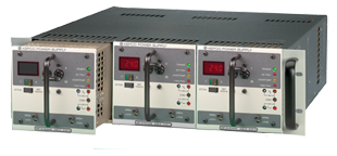
The Kepco HSF/HSP series of hot-swappable power supplies provide N+X redundant
power in modules sized from 50 watts to 1500 watts. All models contain
isolation diodes and circuitry to enable them to share the current into a load.
Built in alarms provide a contact closure that opens on failure of any
individual module. The front panel of each plug-in power module contains an
on-off switch and a "V d-c on" light. When the modules are paralleled, the one
with the highest voltage setting automatically assumes the role of "master" and
its front panel "master on" lamp illuminates. The other modules become
"slaves& and track the voltage setting of the master and share equally in the
load's current. Test points are provided to enable the voltage to be precisely
trimmed to the load¹s requirement.
HSF and HSP are switch-mode power supplies and incorporate aggressive EMI
filtering to reduce the conducted noise below the FCC and VDE 0871 Class B
levels.
The 1000 and 1500 watt HSP occupy just a 5" x 5" cross section so that up to
three modules will fit in a standard 3U x 19" rack housing. Remote on-off
control of the HSP is provided through isolated TTL-level signals powered by an
internal 5V supply. Both the output voltage and the current limit are
controlled through a 20% to 100% range by an external 0-10V analog signal.
Kepco's fault tolerant plug-in power systems will keep a mission critical
system up and running with an extra- ordinarily high level of reliability.
|